


















Machine type
 Prestige XL series (L2, XL2, XL2 Pro, XL3, XL4)
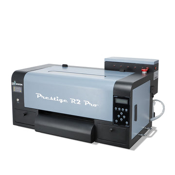
 DTF Station Prestige R2 Pro
 DTF Station Prestige R1
 DTF Station Prestige R2 (original)
 Prestige X6
 DTF Station Prestige A4
 DTF Station Prestige A3+ and A3+ R
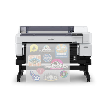
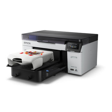
 Epson SureColor G6070 DTF printer
 Mimaki TxF300-1600
 Mimaki TxF330-800
 STS XPD-924D DTF Printer (Mutoh)
 STS VJ-628D DTF Printer (Mutoh)
 DTF Station Vega S17
 STS XpertJet 1682D (XPJ-1682D) 64 inch DTF Printer
 STS XPD-724 DTF Printer (Mutoh)


 Hotronix Fusion IQ, Air Fusion IQ and Dual Air Fusion IQ
 Geo Knight DK20S and DK20SP Digital Knight Swing-Away Presses
 DTF Station Maxima and Proxima Dual Heat Presses
 Hotronix Auto Open Clam and Hover Heat Press
 DTF Station Prisma Auto Heat Press
 DTF Station Prisma Dual Heat Press
 DTF Station Prisma Swing Heat Press
 Insta 718, 728 and 828 Automatic Swing-Away Heat Presses
 DTF Station Prisma Sentry Heat Press
 Geo Knight DC16 and DC16AP Digital Combo Swing-Away Presses
 Geo Knight DK Digital Clamshell Presses: DK20, DK16, DKA Auto, DK8 Label and DK7 Cap
 Hotronix Auto Open Cap Press and 360 IQ Hat Press
 Hotronix Craft Heat Press 9 x 12
 Hotronix Mighty Mug Heat Press
 Insta 256 and 288 Manual Swing-Away Heat Presses
 Insta 907 Dual Station Shuttle Label Heat Press


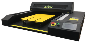
 Viper MAXX pretreatment machine
 Ecofreen Mister-T2 and Mister-T2 Pro pretreatment machines
 Pearl Elite and Pearl PTM DTG pretreatment machines
 Viper XPT-1000 pretreatment machine
 Lawson Silver-Jet and Silver-Jet V2 DTG Pretreat Sprayers
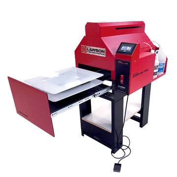
 Lawson Zoom-AE DTG pretreatment machine
 Viper MINI handheld DTG pretreatment machine


Brand
Prestige XL series (L2, XL2, XL2 Pro, XL3, XL4)
DTF Station Prestige R2 Pro
DTF Station Prestige R1
DTF Station Prestige R2 (original)
Prestige X6
DTF Station Prestige A4
DTF Station Prestige A3+ and A3+ R
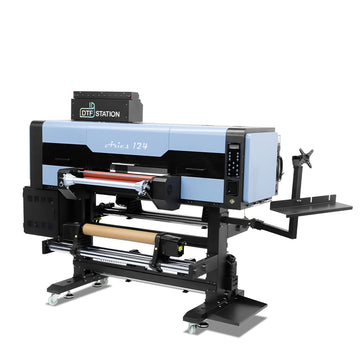
 DTF Station Aries 124 UV DTF printer
 Miro DTF Powder Shakers: Miro 13 Max, 16, 24 and 36
 DTF Station Aries 213 and Aries 113 UV DTF printers
 Seismo L16R and L24R DTF Powder Shaker and Dryer
 Phoenix Air 16x20 DTF Curing Oven
DTF Station Maxima and Proxima Dual Heat Presses
DTF Station Prisma Auto Heat Press
DTF Station Prisma Dual Heat Press
DTF Station Prisma Swing Heat Press
DTF Station Vega S17
DTF Station Prisma Sentry Heat Press
 DTF Station Seismo V36R DTF Powder Shaker and Dryer
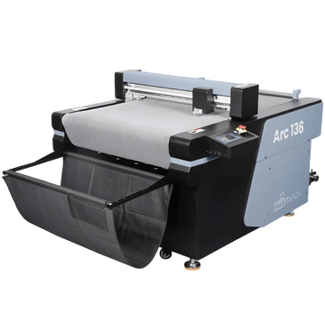
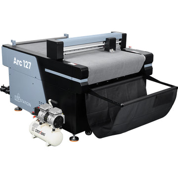
 DTF Station Arc 127 automatic cutter for DTF and UV DTF film
 Epson SureColor F2100
Epson SureColor G6070 DTF printer
 Epson SureColor F2270
 Epson SureColor F3070
 Epson SureColor F570
 Epson SureColor F170
 Epson SureColor F6470 and F6470H
 Epson SureColor F6370
 Epson SureColor F7200
 Epson SureColor P-Series photo printers (P700, P900, P6570, P8570)
 Epson SureColor T-Series CAD and technical printers
 Epson SureColor S-Series (S40600, S60600, S80600)
Vastex V-1000 assembly: stand, rotor arms, wheel lock housings, print heads and lift springs
Build the V-1000 stand first, then the rotor detent, wheel lock housings and rotor arms. Check that every wheel lock housing reads within about half a bubble of the others and shim any that don't. Then mount the hinges, slide in the print heads, hook the lift springs from the outside in and fit the stop bar. Finish by setting each hinge against the same wheel lock housing before you level pallets and heads.
The V-1000 ships in several marked boxes: the center hub assembly, rotor detent, rotor arms with wheel lock housings, hinges and print heads, pallets and hardware. Lay everything out and check it against the box list on page 4 of the manual before you start. You need 1/4, 7/16 and 9/16 in wrenches (or an adjustable wrench), a 9/16 in socket with ratchet and extension, and a level. Tabletop models start at the hinge step.
The print head lift springs are under heavy tension. Take care installing them, never let a head swing up unrestrained, and don't remove springs unless Vastex tells you to.
Build the stand and hub
-
Fit the legs
Open the center hub box and leave the assembly in it. Remove the bolt, washer and lock washer from the bottom, push a leg through both rectangular openings until its angled bracket sits flat on the base plate (the fit is tight, a hammer is fine), and refit the hardware. Repeat for all legs, then carefully turn the press upright. On the V1-88 the stand comes mostly built; fit the fifth leg the same way.
-
Mid pan and wheels
Rotate the mid pan into place and bolt it with four 5/16 in bolts and serrated nuts. If you bought the drop down wheel set, bolt each brace and caster set together and secure one under each leg.
-
Rotor detent
Bolt the detent assembly to any side of the base hub with three 1/4 in bolts. After the rotor arms are on, loosen the lock nut and turn the screw out for more holding pressure or in for less, then retighten. Most presses need only one of the two springs.
-
Wheel lock housings and rotor arms
Bolt a wheel lock housing to each rotor arm using the hole set for your model (the manual shows V1-88, V1-66, V1-46 and 4-color presses). Hang each rotor arm on the hub's hook pins, fit four 3/8 in bolts and locknuts, then go back and tighten them all.
Check the wheel lock housings
This decides whether every head will sit flat on every pallet. Rotate an arm into the detent and lay a level across its side bearings. Stay in the same spot and rotate each arm to you, reading the bubble each time. A difference of up to about half a bubble between arms is fine. If one is further out, mark it with tape, keep the most level housing tight, loosen the four screws on the marked one, slide a shim in on the low side, push the housing toward the center while you retighten, and recheck.
Hinges, heads and springs
-
Mount the hinges
Fit each hinge to the C hub with two 3/8 in carriage bolts through the two outside holes. Install all hinges now.
-
Slide in the print heads
Grease the floating pivot pin and its slots, slide the head into the hinge, and lower it onto the bearings.
-
Hook the lift springs
Pick the spring holes for your screen weight using the chart in the manual. Always hook springs from the outside in: tilt the head back, hook the top (moving) end first, then the bottom end into the hinge. The standard head has one spring per side. The HD head has two per side: the top springs go in the inner hooks first, then the bottom springs in the outer hooks. A second person helps here.
-
Fit the stop bar
Lower the head with the springs seated and slide the stop bar into its slots. It fits one way and has two positions: Operation (the head stops in the up position) and Locked Down (holds the screen down).
-
Set the hinges
Vastex calls this a very important step. Loosen the two hinge mounting bolts half a turn only. Push the head down several times so it seats in the wheel lock bearings. Lower it, move the stop bar to Locked Down, and tighten both bolts firmly. Return the bar to Operation and raise the head. Do every head on the same wheel lock housing.
Pallets
Fit the neck guide if you use one (it's needed for the Vastex Jacket Quick Stretch), slide four leveling bolts into the pallet slots with the washer on the nut side, and attach the pallet arm with nuts left loose. Fit the corner tab, corner nut, hairpin clip and pallet knob, then slide the pallet and arm onto the rotor arm. Now go to pallet leveling and print head leveling before you print. If a part arrived damaged or a hub won't turn freely, text us a photo at (562) 609-4996.
Watch Vastex's video: V-1000 head and pallet leveling (the step after assembly)
More videos
Embedded from the manufacturer's official channel.
Common questions
Do I need help to assemble the V-1000?
Yes. Vastex recommends two or more people. A V1-44 weighs about 256 lb and a V1-88 about 520 lb.
Why is the head not touching the bearings after assembly?
The hinge has not been set. Loosen the two hinge mounting bolts half a turn, push the head down several times, lock it down with the stop bar, then tighten the bolts.
Which spring holes should I use?
It depends on the screen weight and whether you have the standard or HD head. The manual shows positions for screens up to 3 lb and up to 6 lb. The HD head handles screens or attachments up to 20 lb with four springs.
Can I remove the stop bar?
No. Vastex says not to operate without it and only to remove it when removing the whole print head.
How tight should the rotor detent be?
Adjust the detent screw out for more holding pressure and in for less. Most presses need only one of the two supplied springs.
- Vastex V-1000 Printer Assembly and Operations Manual, doc 01-08-042L (PDF)
- AA support requests about Vastex V-1000 parts, 2024 to 2026